Saturday, 16 March 2013

TURBO ANALYSIS & COMBUSTION CHAMBER DESIGN:

               I used the Jet Specs Turbo Analysis software from the following link  http://www.ivcity.com/turbosoft/

          This software gives approximate estimation of some parameters of the turbocharger turbojet. It also provides combustion chamber and flame tube dimensions for the engine. Most DIY turbines use large combustors allowing for proper fuel combustion thereby achieving low exhaust temperature. Commercial gas turbines have fairly small but efficient combustors. However they are more difficult to design .The above softwares only provide dimensions for a large combustor .Since this is my first time I have decided to stick with the proven design.

Here are some screenshots of the software with my turbo's data


Friday, 15 March 2013

TURBOCHARGER SELECTION

THE TURBOCHARGER:

The principle criteria for turbo selection is cost since there will be more costs involved in other parts of the engine .It is better to obtain a good condition used turbocharger .The second criteria is that when it comes to turbochargers for jet engine conversion projects the rule is always the bigger the better. This is because small turbochargers tend to have low turbine efficiencies and mismatched compressor-turbine which is not good for jet engine conversion.The other important criteria is that the turbo should not have a waste gate and it should preferably have a non-divided turbine inlet.


TURBOCHARGER CUT SECTION                             

        The turbo I could find was the Holset HX40 that I found in a used parts market .The turbo was in good condition but needed to be cleaned and lubed for use. However my turbo unfortunately has a divided turbine inlet .I have decided to go ahead with this turbo because it is very hard to find a good used turbo in the used market .I had to reject a lot of turbos with broken blades and other problems till I obtained this.

PREPARING THE TURBOCHARGER:

COMPRESSOR COVER REMOVED

COMPRESSOR

TURBINE

TURBOCHARGER PARTS


PROJECT 2

TURBOCHARGER TURBOJET ENGINE

               The objective of this project is to build a mini turbojet engine using an automotive turbocharger.

 An automotive Turbocharger Uses a Compressor to provide a pressure boost to an engine by increasing the pressure of the air entering the engine’s air inlet .The exhaust from the engine is routed via a turbine in the turbocharger which harvests energy and uses it to run the compressor .This mechanism can be used to make a turbojet engine if the automotive engine is replaced by a gas turbine combustion chamber and by fitting a nozzle to the turbine’s exhaust .


CONCEPTUAL DESIGN:


Saturday, 12 January 2013

ENGINE TEST VIDEOS

DAY TEST VIDEOS:


NIGHT TEST VIDEOS:


Friday, 11 January 2013

IGNITION SYSTEM & TESTING


IGNITION SYSTEM:
     • In order to maintain simplicity in the fabrication process
        and to reduce cost sparkler ignition system was used.
     • The sparkler is ignited and dropped into the engine
        before supplying fuel and compressed air for starting the engine.

SPARKLER AND MATCH BOX
TEST RUN: 
            Before operation the engine was tested for any leaks by filling it with water. This way any cracks or leaks in the welds can be identified and rectified .However there was no such leak in the engine. 
            Testing was done in two configurations ,horizontal mount and vertical mount.
It was extremely difficult to start the engine in the  horizontal configuration  as the sparkler needs to be pushed sideways into the engine's combustion chamber .In the vertical configuration it can just be dropped into the exhaust and gravity will do the rest.
Here aresome images of the test run.Will be uploading some videos soon .

HORIZONTAL 


HORIZONTAL

VERTICAL


VERTICAL


RED HOT AFTER A FEW SECONDS OF RUNNING


VERTICAL(the brown pipe is an extension to the blower)

             The blower is used for initial compression of air for the engine .The blower air is fed through the engine's inlet . Once the engine self sustains the blower is turned off and the engine continues to run .A continuous run for about 40 seconds results in the combustion chamber and the surrounding areas becoming red hot.              

VALVELESS PULSEJET ENGINE

PROJECT 1VALVELESS PULSE-JET ENGINE
         
              
        Valveless pulse jet (or pulsejet) is one of the simplest jet propulsion devices ever designed, and is the simplest form of jet engine that does not require forward motion to run continuously. Valveless pulsejets are low in cost, light weight, powerful and easy to operate. They have all the advantages (and most of the adisadvantages) of conventional valved pulse jets, but without the troublesome reed valves that need frequent replacement - a valveless pulsejet can operate for its entire useful life with practically zero maintenance. They have been used to power model aircraft, experimental go-karts and even some unmanned military aircraft such as cruise missiles and target drones.


HISTORY:

GERMAN V1 BOMB
       
       The pulsejet engine was first invented in the early 1900 by a Swedish inventor Martin Wiberg


       Paul Schmidt, who engineered the first production pulsejet during the Second World War with his flying bomb, the Argus V1.

           Nicknamed the “buzz” bomb because of the low hum it emitted 
           during flight.
           Used by the Germans to bomb London from 1944-1945.
           Over 9,000 V-1 were fired on England during WW2.
       The pulsejet took a backseat in the engineering world when the turbofan jet engine was invented
       Has returned to the engineering scene as of late because of the interest in Pulse Detonation Engines (PDE).

 HOW IT WORKS:


       The "valveless" pulsejet is not really valveless — it just uses the mass of air in the intake tube as its valve, in place of a mechanical valve. It cannot do this without moving the intake air outward, and this volume of air itself has significant mass, just as the air in the tailpipe does — therefore, it is not blown away instantly by the deflagration but is accelerated over a significant fraction of the cycle time. In all known successful valveless pulsejet designs, the intake air mass is a small fraction of the tailpipe air mass (due to the smaller dimensions of the intake duct). This means that the intake air mass will be cleared out of contact with the body of the engine faster than the tailpipe mass will. The carefully designed imbalance of these two air masses is important for the proper timing of all parts of the cycle.


VALVED AND VALVELESS PULSEJETS: 
        
       •Valved:
 Pedal or spring valve construction
 Harder to build
 More Expensive
Valve-less:
 No moving parts
 Easier to build
 Cheaper 


DESIGN:
            
     This engine was built in January 2012. Back then I had no idea that I will be creating jetprojects blog  So   I didn't click pictures during fabrication of the engine.However the CAD models and testing pictures and videos are available .I believe that  the following information will be useful to all DIY jet engine enthusiasts.
           
      The main objective of the design was to make the engine as simple as possible. So I limited myself to simple cylindrical structures  . Initially a rough hand sketch of a simple design was made on an A4 sheet. Later a 3D model was generated using Solid Works .


COMBUSTION CHAMBER
INLET
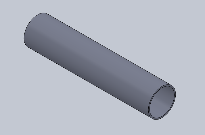
EXHAUST
COMPLETE ENGINE


FABRICATION:


      The entire engine was made from SS304(stainless steel) Sheets and
         SS304 pipe.
      The inlet and combustion chamber were rolled from SS304 sheet.
      The exhaust is an SS304 pipe.
      The three parts were welded together by MIG welding at a welding
         Work Shop.
      The rolling process and welding process were done in the
         Workshop.
      The fuel injector was made by bending and welding copper tubes.


COMPLETED ENGINE:


FUEL  SYSTEM:
    
           LPG was used a fuel for running the engine .
                A 15kg LPG cylinder was used.
                An LPG gas tube was used to link the cylinder outlet to the
              fuel injector.
           A  high flow rate LPG regulator was also used to provide high
                 fuel flow into the engine’s combustion chamber

LPG (PROPANE CYLINDER)
RUBBER TUBE
        
HIGH FLOW RATE REGULATOR


FUEL INJECTOR: